Thanks Nudge. Not sure what Shellac is over there, but here it's similar to varnish.
Over on another forum, the guys could not speak highly enough of Loctite 515. So I've purchased a tube of that and I'll be reassembling soon.
In the meantime I want to dig a little deeper and find out more about the fore and aft compression seals fitted to this engine. Presumably these act to seal the crank case where crank shaft exits the end bells.
As I literally cant see them, I will need to remove the bearing from the fore end bell to see exactly what type of seal is used and what condition it’s in. I’m half expecting that the bearings themselves will be sealed eg 1RS or 1Z or similar but really don’t know for sure. Regardless, if what I find looks dodgy, then I'll probably need to make up a tube spanner to remove the clutch assembly and aft end bell as well.
The reason I am now motivated to check these whereas I was not so much before, is because I noted a potential problem whilst flushing the rear end bell before painting. I had the engine in a vertical position (flywheel side up) and poured kero into the aft end bell and was surprised to see it leak out seemingly without restriction.
I am therefore not sure if I have a failed seal, or if it has been inadvertently dislodged during separation of the crank case. To explain that further, the fore end bell was fixed tight and needed some gentle persuasion with rubber mallet to slide off the shaft. Is it possible that the crank shaft also moved forward also along with the aft bearing and seal? I will need to take some measurements or do a mock reassembly to confirm.
The manual is poor in terms of content both written and illustrative, so I’m sort of flying blind here.
Will update when I know more.
Thanks and regards,
S
Stuart P55MR
Moderators: John@sos, charlesp, Charles uk, RickUK, Petergalileo
Re: Stuart P55MR
www.vintageoutboardsaustralia.blogspot.com
Re: Stuart P55MR
Yup that's the same stuff , mix it with methylated spirits to thin / clean up.
Thanks Nudge. Not sure what Shellac is over there, but here it's similar to varnish.
That is a good product , used that too!Over on another forum, the guys could not speak highly enough of Loctite 515. So I've purchased a tube of that and I'll be reassembling soon.
Keep up the good work.
"THE KING OF BLING"!
Is it better to over think, than not think at all?
Is it better to over think, than not think at all?
Re: Stuart P55MR
G'day all, just thought I'd do a quick update. This is where we're at with the Stuart as of a few moments ago.
* All bar the gear shift assembly has been thoroughly cleaned, reworked as necessary and painted.
* Color has been changed from Deep Brunswick Green to Mid Brunswick Green.
* All brass components have been cleaned, but are yet to receive final polish and clear coat.
* Still need to pick up some BSF hardware and a couple of replacement circlips, make a few gaskets and hone the cylinders before final assembly. Also need to pick up some retro spark plug leads and fittings just to give it a more original look.
Rough assembled just to get as much as possible in the pics.


Hope you enjoy.
Regards,
Spiro
* All bar the gear shift assembly has been thoroughly cleaned, reworked as necessary and painted.
* Color has been changed from Deep Brunswick Green to Mid Brunswick Green.
* All brass components have been cleaned, but are yet to receive final polish and clear coat.
* Still need to pick up some BSF hardware and a couple of replacement circlips, make a few gaskets and hone the cylinders before final assembly. Also need to pick up some retro spark plug leads and fittings just to give it a more original look.
Rough assembled just to get as much as possible in the pics.
Hope you enjoy.
Regards,
Spiro
www.vintageoutboardsaustralia.blogspot.com
-
AusOB_Collector

- Posts: 293
- Joined: Tue Apr 07, 2015 2:04 pm
- Location: Perth, Western Australia
- Contact:
Re: Stuart P55MR
Spiro
She is beautiful!! Am looking forward to the first run video!
Did you end up getting the P55 in Bunbury?
Cheers
BP
She is beautiful!! Am looking forward to the first run video!
Did you end up getting the P55 in Bunbury?
Cheers
BP
Too many Seagulls to count now!
Member SOS, AOMCI,
President of AOMCI's WOOC chapter
Member SOS, AOMCI,
President of AOMCI's WOOC chapter
-
Collector Inspector

- Posts: 4182
- Joined: Sun Jun 29, 2008 4:32 am
- Location: Perth Western Australia
- Contact:
Re: Stuart P55MR
Thanks guys.
Still a ways to go, but getting closer.
Friend at work thinks his father (vintage auto restorer) may have a Whitworth tube spanner of the right size. If he's proven right, crank case will come apart (again) and shaft seals will be replaced. Worth the effort IMO.
As you can see from the pic of the barrel studs laid side by side below, there has been an issue with galvanic corrosion at the head gasket. Question I have now is what's a suitable alternative considering limited only future use of the engine?

Original copper gasket is damaged anyway, and cannot be re-used.
Regards,
S
Still a ways to go, but getting closer.
Friend at work thinks his father (vintage auto restorer) may have a Whitworth tube spanner of the right size. If he's proven right, crank case will come apart (again) and shaft seals will be replaced. Worth the effort IMO.
As you can see from the pic of the barrel studs laid side by side below, there has been an issue with galvanic corrosion at the head gasket. Question I have now is what's a suitable alternative considering limited only future use of the engine?
Original copper gasket is damaged anyway, and cannot be re-used.
Regards,
S
www.vintageoutboardsaustralia.blogspot.com
Re: Stuart P55MR
Looking Great !!
Is your Question about replacing the Studs, or the Head Gasket ? .
I would reuse the Studs. As for the Head Gasket, get one made in copper, or suitable Head Gasket material, and it should be good for many years.
Cheers
Is your Question about replacing the Studs, or the Head Gasket ? .
I would reuse the Studs. As for the Head Gasket, get one made in copper, or suitable Head Gasket material, and it should be good for many years.
Cheers
Re: Stuart P55MR
Hi Mark, question was about alternative head gasket material. I want to avoid copper of possible.
Any suggestions?
Regards
S
Any suggestions?
Regards
S
www.vintageoutboardsaustralia.blogspot.com
Re: Stuart P55MR
Not a heck of a lot done to the Stuart in the last couple of weeks, however there has been a little progress.
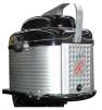
Control column has been disassembled, cleaned, primed and painted and is almost ready for reassembly. One grease (oil) nipple removed, other remaining as seen in the pics below will be removed also, before both are replaced with new.


With regards to nut securing the clutch cone and in turn the crank shaft, I did the unthinkable and read through the various P55 and P66 manuals I’ve been able to download from the net. One comprised a section headed “special tools needed for complete overhaul” and in that was mention of an 5/8 x 11/16BSF tube spanner. BINGO!
 [/URL]
I was able to purchase 7 old tube spanners for a grand total of $5.00 at the Castlemaine Swap yesterday. By chance, one of those proved to be a perfect fit and the nut was off within minutes albeit that I needed to use the rattle gun.
By that time however, dark was rapidly approaching so I’m yet to remove the clutch cone.

Once the clutch cone has been removed, I expect I will be able to access/remove the sprocket/chain drive for the magneto and water pump. I envisage those will need to removed also before the crank case is pulled down one final time to allow for the crank shaft seals to be replaced.
Hopefully, it will all be as easy as it sounds above.
Regards,
S
Control column has been disassembled, cleaned, primed and painted and is almost ready for reassembly. One grease (oil) nipple removed, other remaining as seen in the pics below will be removed also, before both are replaced with new.
With regards to nut securing the clutch cone and in turn the crank shaft, I did the unthinkable and read through the various P55 and P66 manuals I’ve been able to download from the net. One comprised a section headed “special tools needed for complete overhaul” and in that was mention of an 5/8 x 11/16BSF tube spanner. BINGO!
[/URL]I was able to purchase 7 old tube spanners for a grand total of $5.00 at the Castlemaine Swap yesterday. By chance, one of those proved to be a perfect fit and the nut was off within minutes albeit that I needed to use the rattle gun.
By that time however, dark was rapidly approaching so I’m yet to remove the clutch cone.
Once the clutch cone has been removed, I expect I will be able to access/remove the sprocket/chain drive for the magneto and water pump. I envisage those will need to removed also before the crank case is pulled down one final time to allow for the crank shaft seals to be replaced.
Hopefully, it will all be as easy as it sounds above.
Regards,
S
www.vintageoutboardsaustralia.blogspot.com
Re: Stuart P55MR
Looking sweet!
I was almost going to suggest to cut a scoket down and weld it to a length of pipe to get the nut off. Good to see you found the correct parts.
I was almost going to suggest to cut a scoket down and weld it to a length of pipe to get the nut off. Good to see you found the correct parts.
"THE KING OF BLING"!
Is it better to over think, than not think at all?
Is it better to over think, than not think at all?
Re: Stuart P55MR
Thanks Nudge,
Decided it didn't make a whole lot of sense to continue the rebuild without replacing all the seals. It means more work now, but a better restoration in the end.
Regards,
S
Decided it didn't make a whole lot of sense to continue the rebuild without replacing all the seals. It means more work now, but a better restoration in the end.
Regards,
S
www.vintageoutboardsaustralia.blogspot.com
Re: Stuart P55MR
What is the size of the pistons? they look a bit like a seagull one!
"THE KING OF BLING"!
Is it better to over think, than not think at all?
Is it better to over think, than not think at all?
Re: Stuart P55MR
Similar in design maybe, but that's where it ends I think.
The ST P55 has a 2.75" bore and 2.75" stroke. Total capacity is 536cc over the two cylinders and 8bhp at 1500rpm.
Pistons are made of cast iron, this includes the ring locators/pins which form part of the casting. Rings are also much wider than those on a Seagull but I'm yet to measure.
Clutch cone now off. Struggling to remove one of the screws (ie without applying heat) which secure an intermediate section that gives access to the pump/magneto drive sprocket. Needless to say, the sprocket and key need to come off before the crank can be pulled from the crank case.
Will post photos as there's nothing currently on the web to guide restorers through this process. Manual is also pretty useless describing the various related parts and the disassembly/reassembly process.
Not difficult actually, however with the assistance of photos and text here etc, at least anyone venturing is not going in blind.
Regards,
S
www.vintageoutboardsaustralia.blogspot.com
Re: Stuart P55MR
As indicated above, it did not make a whole lot of sense to progress the restoration without replacing the shaft seals which were of an unknown condition. The 11/16BSF tube spanner found at the swap allowed removal of the clutch cone holding nut, without which access to at least the rear crank seal is impossible.
Parts from left to right ie indicating removal procedure; clutch cone holding nut, clutch cone, 2 x shaft keys, intermediate plate fixing screws and washers (1 screw MIA), intermediate plate & external shaft bearing, spacer, magneto/water-pump drive sprocket.

With these parts removed as well as the 4 nuts that at the forward crank case, it is possible to separate the forward and rear crank case sections from the crank shaft ie leaving the center crank case sections and crank shaft intact. This eliminates the need to realign the center bearing which can be a right pain in the butt.
The forward and rear crank case sections each house the crank shaft bearings and seals. The bearings must be removed to access the seals which are essentially pressed in to their respective housings.
The original seals are a great piece of engineering in themselves. Each is like a fat washer that comprises a groove along its outer perimeter, which house a couple of compression rings.
Forward crank shaft seal

Rear crank shaft seal

The modern replacements are far less interesting and made from a synthetic rubber material, a typical oil seal as seen in the image below. The larger of the 3 seals is a replacement drive shaft seal. The grease nipples and circlip are for the control column.

Whilst there is plenty already planned for the coming weekend, I’m hoping that I will be able to block out some time to reassemble the bottom half of this engine.
Regards,
S
Parts from left to right ie indicating removal procedure; clutch cone holding nut, clutch cone, 2 x shaft keys, intermediate plate fixing screws and washers (1 screw MIA), intermediate plate & external shaft bearing, spacer, magneto/water-pump drive sprocket.
With these parts removed as well as the 4 nuts that at the forward crank case, it is possible to separate the forward and rear crank case sections from the crank shaft ie leaving the center crank case sections and crank shaft intact. This eliminates the need to realign the center bearing which can be a right pain in the butt.
The forward and rear crank case sections each house the crank shaft bearings and seals. The bearings must be removed to access the seals which are essentially pressed in to their respective housings.
The original seals are a great piece of engineering in themselves. Each is like a fat washer that comprises a groove along its outer perimeter, which house a couple of compression rings.
Forward crank shaft seal
Rear crank shaft seal
The modern replacements are far less interesting and made from a synthetic rubber material, a typical oil seal as seen in the image below. The larger of the 3 seals is a replacement drive shaft seal. The grease nipples and circlip are for the control column.
Whilst there is plenty already planned for the coming weekend, I’m hoping that I will be able to block out some time to reassemble the bottom half of this engine.
Regards,
S
www.vintageoutboardsaustralia.blogspot.com
Re: Stuart P55MR
so Im guessing that the oid seals where bad?
If it where me I would have made new seals the same as the old ones (I have a lathe and mill so it is easy for me)
If it where me I would have made new seals the same as the old ones (I have a lathe and mill so it is easy for me)
"THE KING OF BLING"!
Is it better to over think, than not think at all?
Is it better to over think, than not think at all?